 Make sure you’ve already made the Light Actuated Circuit before starting this project!
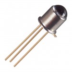
Photoresistors (also called CdS photocells) are made of a material that reacts with light, very similar to solar cells. When light hits the material, it knocks a few electrons loose. When you hook up the cell to a circuit, the electrons now have a place to go, and electricity flows through your wires. You’ll notice your CdS cell works when you shine a light on it from either the front side or the back side. If you want to use a phototransistor, make a note as to the frequency of light it’s been tuned to – some will only work with IR light (like your remote control or sunlight).
In this circuit, the LED is actuated only when the photoresistor is dark. If you want a faster response to your light, you can substitute a phototransistor for the photoresistor (CdS cell) and adjust the value of the 1-kOhm resistor (change it lower or higher, or use a potentiometer) to control the sensitivity.
This is basically the same as the light-actuated circuit. The difference is that the transistor is connected to control power to the LED in the opposite way as the light-actuated circuit. So, as there is more light on the photocell (and the base lead gets more current), the voltage to the transistor is reduced.
Click here for Unit 14 (Lesson 1) schematics.
Notice what is the same in the circuit, and what is different.
Materials:
- breadboard
- AA battery case
- 2 AA batteries
- LED
- CdS photocell
- transistor (2N2222A)
- 4.7k resistor
- 1k resistor
- jump wires
- wire strippers


I think you are referring to the “light-actuated” circuit in the previous lesson. The 4.7K resistor and the CdS cell / 100Ω Resistor are an example of a voltage divider. Resistance in the CdS cell is lowest when exposed to light.
When light shines on the CdS cell, resistance is low. This causes the base of the resistor to receive a positive voltage, causing the LED to glow.
When the CdS cell is covered, its resistance increases, causing voltage to decrease towards ground.
Why do you need a 4.7K resistor linking the transistor to the negative power when a negative charge is needed to ‘open’ the base ‘gate’? Also, why won’t it work when you put it on the other side of the transistor base wire( a jumper connects the transistor to the negative bus) with the CdS cell and 100K resistor plugged in in series with the 4.7K resistor? THANKS.
Yes, it is possible to blow resistors if too much power flows through them. But as long as you keep all the other parts connected as shown, the power through the resistor is low enough to keep it safe.
Is it possible to blow a Resistor? I feel a bit timid to try out a different resistor than the one you list .