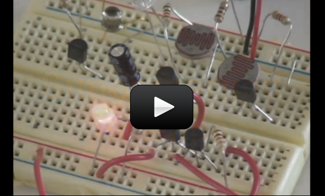

In this circuit, we’re going to use a special kind of resistor, called a CdS photocell to detect light and dark. When light is shined on the photocell, the LED will light up. When it is dark, the LED goes out. And with just a little light, the LED is dim. Remember the explanation of how a transistor works? We talked about having a small voltage (or current) control a larger one, kind of like turning the knob on a light switch dimmer in your house? That’s what this circuit is doing.
The photocell is a kind of resistor that changes it’s resistance depending on how light or dark it is. In this circuit, when it is light, the photocell delivers more current to the base lead of the transistor. When this happens, the transistor allows more voltage to flow from the emitter lead to the collector lead, which in turn lights up the LED. One resistor are simply used to reduce the amount of current that goes into the transistor (so it doesn’t get too much current) if the photocell has a really low resistance because of how much light is on it. The other one is called a pull-down resistor. Think of it like a door closer spring for electricity. A door closer closes the door when you let go of it (instead of leaving the door to sway in the wind). A pull-down resistor makes sure that when the transistor is “off”, it will “spring” toward a connection to the negative side of the battery (a pull-up makes it spring toward the positive).
If this is all confusing, don’t worry. It will make more sense as you build more circuits and look at more schematic diagrams.
Click here for Unit 14 (Lesson 1) schematics.
This light-actuated relay circuit will remain actuated for a brief time after you remove the light. You can substitute a 1.5-3V buzzer for the LED if you’d rather have a loud circuit.
Materials:
- breadboard
- AA battery case
- 2 AA batteries
- LED
- CdS photocell
- transistor (2N2222A)
- 4.7k resistor
- 1k resistor
- jump wires
- wire strippers
Here’s what you do:
You’re welcome and great job! Nope, the order doesn’t matter as long as they are on the same numbered row and on the same side of the valley that goes down the middle of the board.
When looking at a numbered row, there are five holes, a little valley, and then five more holes. The five holes on the “top” of the valley and the five holes on the “bottom” are not connected to each other. Perhaps had one of the wires on the other side of that valley?
Another possibility is that there was just a bad connected between one of the wires and the connection inside the breadboard. When you unplugged and re-plugged each connection it may have resolved the bad connection.
Thank you for answering my questions, and HORAAAYYYY!!!!!!!!!
After 5 more times of re-doing and trouble-shooting this circuit, my buzzer is light-activated!!!
I can put my finger over the CdS cell and it stops buzzing, and when I remove my finger it is buzzing again!
QUESTION: In the final steps of connecting the circuit: Does it matter in what order I stick the Resistor wire (in front or behind the collector of the Transistor), so long as the Resistor is in the same row of the collector?
I notice the CdS, the collector of the Transistor, and the Resistor are all in the same row. So, if I messed up the order to be: collector, resistor, CdS- but it was all in the correct row, could that be why my CdS cell wasn’t working earlier?
Regarding your first question: Generally speaking, a resistor must always be provided on the base of transistors and in line with LEDs. This protects those devices from receiving too much current, which would damage those parts.
In circuits 1, 2 & 3, notice how a fixed resistor is connected to one side of the battery and the CdS cell is connected to the other side. Both these resistors are needed to properly control the brightness of the LED. Please see the explanation for this circuit on this page for more details on the purpose of these resistors.
Regarding your second question: CdS cells are very tough, and usually only become damaged if too much current flows through them and can easily handle the current from two AA batteries.
To test your CdS cells, set your multimeter to measure resistance (Ω) and connect one probe to each side of the CdS. You should see a measurement between 10K (10,000) and 20K (20,000) ohms. When you cover the CdS or shine a light on it, the resistance should change. If you see those results, the CdS is working properly.
Based on your description, possibilities come to mind: You mostly like have a bad transistor, or you have an incorrect connection that is allowing current to flow directly to the LED.
Start by clearing your breadboard and build your circuit from scratch. Double check the value for each resistor as you place it and double-check the part number for each transistor. Be sure to follow each connection as it is shown on the video. Be sure each pin of the transistor is in a separate numbered column.
If your circuit still does not work, try swapping out the transistor with a new one (be sure it has the same part number).
Why are resistors needed on this circuit? Why can’t it just have the transistor?
Also: I tried this experiment three times and still can’t get my CdS cell to control the current.
I plug in the battery and the LED lights up whether I cover the CdS cell or not. Tried another CdS cell to see if it just might be a dud, but the second one does the same.
Also tried a buzzer. Buzzer went off whether I covered the CdS cell or not. Do you think I might have 2 CdS cell duds?
It’s the same transistor.
Hi,
On this item you say we need transistor (2N2222A). On Bread Board Basics we need transistor (NPN 2N2222A). Does the one having an NPN in front of it make a difference or is it the same item?
Thank you,
Michelle
I’ll have my team connect with you right away.
we don’t seem to ave access – can you grant this please? To the entire lesson? Thanks!
Without actually seeing the experiment and wiring, my first guess based on your description is the transistor. be sure it’s the right one, that it’s in correctly, and it hasn’t been burned out. If my circuit didn’t work (which happens ALL the time), I go back and trace back through it while watching the video. Being able to troubleshoot effectively is just as important as doing the experiment itself. It’s one of the most used skills in engineering, so keep trying…I know you can do it!!
My son completed this project but said the light just stays on. I will have him do it again, but can you tell me a reason it might not have worked? He also completed the next project where the light should turn on in the dark and off in the light and it does just the opposite.
Whoops – sorry about that! Once in a while the audio gets stripped off when the videos are rendered and uploaded. The new file is being uploaded right now – try again soon?
Hi Aurora.
I came to watch this video and it seems to have no sound.
Just wondering if you could solve it for me.
Thanks.