Let’s see how much you’ve picked up with these experiments and the reading – answer as best as you can. (No peeking at the answers until you’re done!)  You can also print these out and jot down your answers in your science notebook.
Click here for a printer-friendly version of the exercises and answers for Unit 14.
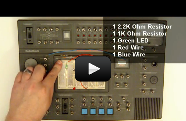
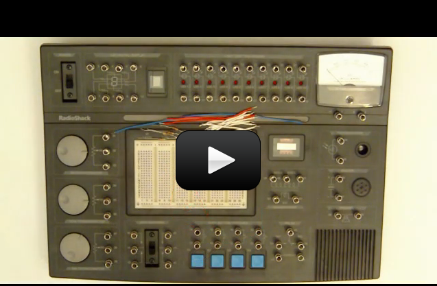
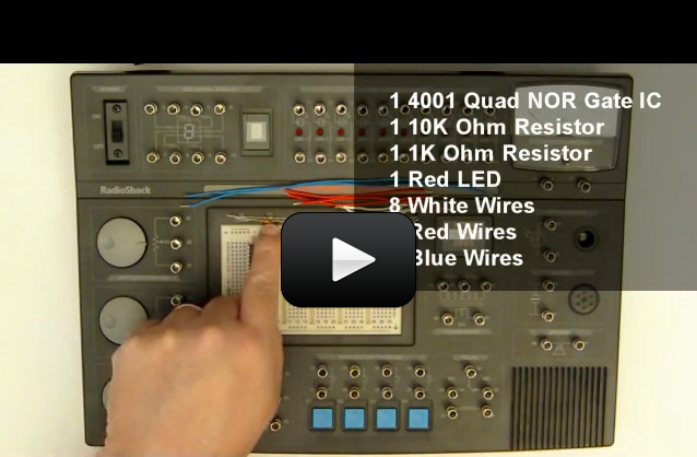
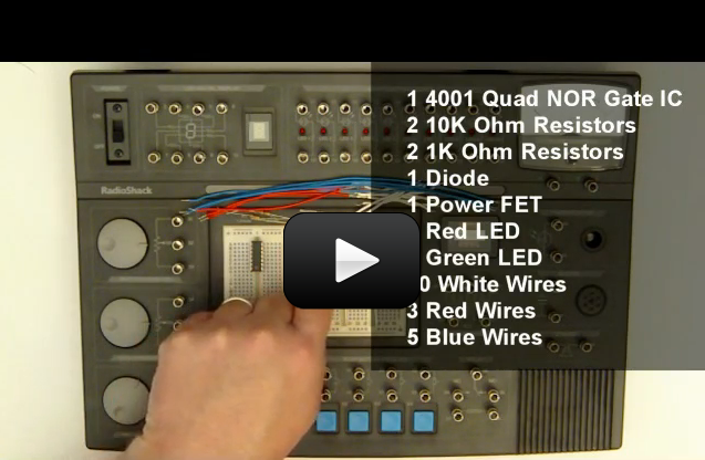

[am4show have=’p9;p51;’ guest_error=’Guest error message’ user_error=’User error message’ ]


1. What is a bit?


2. What is a nibble?


3. What is a byte?


4. What is a logic gate?


5. What is a truth table?


6. If we have a NAND gate with both inputs low, what is the output?


7. If we have an OR gate with both inputs low, what is the output?


8. If we have a NOR gate with both inputs low, what is the output?


9. What is a pull-down resistor?


10. What is a pull-up resistor?


11. How many gates are required to build a digital oscillator?


12. What is a SR Latch?


13. What is an inverter?


14. What is a D type Flip Flop?


15. What is switch bounce?


16. How can we solve switch bounce?


17. What is a seven segment display?


18. Why do we use seven segment displays?


19. What is a binary coded decimal counter?


20. What does a binary coded decimal to seven segment display IC do?


[/am4show]


Let’s see how you did! If you didn’t get a few of these, don’t let it stress you out – it just means you need to play with more experiments in this area. We’re all works in progress, and we have our entire lifetime to puzzle together the mysteries of the universe!


Answers:
[am4show have=’p9;p51;’ guest_error=’Guest error message’ user_error=’User error message’ ]


1. What is a bit?
A bit represents a logic 1 or a logic 0.


2. What is a nibble?
A nibble is a collection of four bits, also called a “four bit word”.


3. What is a byte?
A byte is 8 bits or two nibbles.


4. What is a logic gate?
A digital logic device that controls its output based on the values of the gate’s inputs.


5. What is a truth table?
A truth table shows us what a digital ICs output should be based on the combination of possible inputs.


6. If we have a NAND gate with both inputs low, what is the output?
High.


7. If we have an OR gate with both inputs low, what is the output?
Low.


8. If we have a NOR gate with both inputs low, what is the output?
High


9. What is a pull-down resistor?
A resistor that is used to force the voltage on a digital input or output to ground.


10. What is a pull-up resistor?
A resistor that is used to force the voltage on a digital input or output to positive voltage.


11. How many gates are required to build a digital oscillator?
2.


12. What is a SR Latch?
A basic digital memory circuit.


13. What is an inverter?
An inverter will output the opposite of what is being input. So if a 1 is on the input of an inverter then the inverter will output a 0.


14. What is a D type Flip Flop?
A memory circuit that can be set, cleared, and also have data clocked in. The D type flip flop also has two outputs, the first is equal to the stored data and the seconds is the inverted value of the stored data.


15. What is switch bounce?
The electrical noise a switch generates when closing or opening.


16. How can we solve switch bounce?
Capacitors can be used to absorb the “electrical noise” from a switch.


17. What is a seven segment display?
A group of seven LEDs arranged to form a pattern in the shape of the number eight.


18. Why do we use seven segment displays?
To translate computer data into information people can easily understand.


19. What is a binary coded decimal counter?
An IC that counts like we do, but stores the data in binary.


20. What does a binary coded decimal to seven segment display IC do?
It takes the BCD data from a counter (or other source) and converts it to the data a seven segment display needs to display numbers people can understand.


[/am4show]


Digital electronics can be a lot of fun and there are some really cool components in the market. So to get us going, in this video we’ll take a look at what digital is and start looking at how it works.


[am4show have=’p9;p51;p103;p107;p108;’ guest_error=’Guest error message’ user_error=’User error message’ ]


[/am4show]


Expanding on the first video for workbook 2, in this video we’ll take a look at logic gates, what they are, and how they work. This includes the AND gate, NAND gate, OR gate, and NOR gate.


[am4show have=’p9;p51;p103;p107;p108;’ guest_error=’Guest error message’ user_error=’User error message’ ]


[/am4show]


Time to start building some circuits, in this experiment we’ll use a 4049 hex inverter IC to build a simple logic probe. Logic probes are used to assist in debugging digital electronics.


[am4show have=’p9;p51;p103;p107;p108;’ guest_error=’Guest error message’ user_error=’User error message’ ]


[/am4show]


In this video we’ll take a look at truth tables, what they are, and why we need them. We’ll also build a simple circuit and construct a truth table from that circuit.


[am4show have=’p9;p51;p103;p107;p108;’ guest_error=’Guest error message’ user_error=’User error message’ ]


[/am4show]


Okay, time to have some more fun with LEDs. In this experiment we’ll build a simple LED flasher and see how we can use two NOR gates to create an oscillator.


[am4show have=’p9;p51;p103;p107;p108;’ guest_error=’Guest error message’ user_error=’User error message’ ]


[/am4show]


In this experiment we’ll modify the LED flasher to use two LEDs and have an adjustable flash rate using a potentiometer.


[am4show have=’p9;p51;p103;p107;p108;’ guest_error=’Guest error message’ user_error=’User error message’ ]


[/am4show]


Want to know how computers remember things? Well, in this experiment we will use two NOR gates to build a Set-Reset latch, which is a simple digital memory storage circuit.


[am4show have=’p9;p51;p103;p107;p108;’ guest_error=’Guest error message’ user_error=’User error message’ ]


[/am4show]


Okay, let’s get a little deeper into electronics and build a control gate. We’ll see how we can use a logic gate to control when a circuit is active and when it’s not.


[am4show have=’p9;p51;p103;p107;p108;’ guest_error=’Guest error message’ user_error=’User error message’ ]


[/am4show]


In this experiment we are going to combine a SR latch with an power FET and build a latched relay. And, we’ll see how we can use low power components to control high power circuits.


[am4show have=’p9;p51;p103;p107;p108;’ guest_error=’Guest error message’ user_error=’User error message’ ]


[/am4show]


Now, let’s have some more LED fun. In this experiment we’ll see how to use three inverters to build a dual LED flasher.


[am4show have=’p9;p51;p103;p107;p108;’ guest_error=’Guest error message’ user_error=’User error message’ ]


[/am4show]


Want to see how computers add? Well, in this experiment we are going to use a exclusive OR gate to build a binary half adder to get an idea of how computers add numbers. This is a critical lesson in understanding binary and how binary numbers are added together, we’ll also expand on this experiment in the next video.


[am4show have=’p9;p51;p107;p103;p108;’ guest_error=’Guest error message’ user_error=’User error message’ ]


[/am4show]


Let’s take a closer look at the NAND gate and how it works, so in this experiment we’ll build a circuit to test the NAND gate and also create a truth table to prove the NAND gate is working correctly.


[am4show have=’p9;p51;p103;p107;p108;’ guest_error=’Guest error message’ user_error=’User error message’ ]


[/am4show]


More LED fun! In this experiment we’ll see who we can combine a 555 timer, a single NAND gate, and make an alternating LED flasher. This circuit will alternate (turn on and off) a green LED and a red LED.


[am4show have=’p9;p51;p103;p107;p108;’ guest_error=’Guest error message’ user_error=’User error message’ ]


[/am4show]


There are a lot of different types of logic gates and in this experiment we’ll see how we can use three NAND gates to make an OR gate. And then we’ll test the gate and create a truth table to prove that the OR gate is working correctly.


[am4show have=’p9;p51;p103;p107;p108;’ guest_error=’Guest error message’ user_error=’User error message’ ]


[/am4show]


Let’s make some noise! In this experiment we’ll use two NAND gates to create a simple oscillator and tie that into the speaker and we’ll see how easy it is to make a tone generator using just a few parts.


[am4show have=’p9;p51;p103;p107;p108;’ guest_error=’Guest error message’ user_error=’User error message’ ]


[/am4show]


The tone generator is nice, but we can make it better. So, in this experiment we’ll modify the tone generator from page 46 of workbook 2 to have an adjustable frequency and volume.


[am4show have=’p9;p51;p103;p107;p108;’ guest_error=’Guest error message’ user_error=’User error message’ ]


[/am4show]


Let’s take the tone generator a step further and add in a second frequency generator and pulse the tone out to the speaker. In this experiment we’ll see how to do just that.


[am4show have=’p9;p51;p103;p107;p108;’ guest_error=’Guest error message’ user_error=’User error message’ ]


[/am4show]


A half-adder is nice, but it’s not providing all the information we need to fully see what’s going on. So, in this experiment we’ll build upon the half-adder from experiment 53 in workbook 2, and turn the half-adder into a full-adder.


[am4show have=’p9;p51;p103;p107;p108;’ guest_error=’Guest error message’ user_error=’User error message’ ]


[/am4show]


Digital locks are pretty neat and in this experiment we are going to build one. We’ll use a lot of different logic ICs to build a digital comparator, which can be used as a combination lock to protect valuables.


[am4show have=’p9;p51;p103;p107;p108;’ guest_error=’Guest error message’ user_error=’User error message’ ]


[/am4show]


Your Electronics Learning Lab includes a 4066 switch IC and in this video we’ll take a look at how this IC works by building a simple LED indicator circuit.


[am4show have=’p9;p51;p103;p107;p108;’ guest_error=’Guest error message’ user_error=’User error message’ ]


[/am4show]


Okay, let’s dive a little deeper into digital memory by taking a look at a data type flip-flop. We’ll see how this logic IC works by building a simple LED display interface and control the flip-flop using switches.


[am4show have=’p9;p51;p103;p107;p108;’ guest_error=’Guest error message’ user_error=’User error message’ ]


[/am4show]


Would you like to see a digital circuit do a little division? Well, in this experiment we’ll build on our knowledge and build a divide-by-two circuit using an inverter IC the 4013 D-type flip-flop. This circuit is also the basis for the LED chaser circuit we’ll build later in the series.


[am4show have=’p9;p51;p103;p107;p108;’ guest_error=’Guest error message’ user_error=’User error message’ ]


[/am4show]


Let’s take a look at binary addition and build a 2-bit counter. In this experiment we’ll modify the divide-by-two circuit we built in the last video to a 2-bit binary counter.


[am4show have=’p9;p51;p107;p103;p108;’ guest_error=’Guest error message’ user_error=’User error message’ ]


[/am4show]


Time for some light chasing fun. In this experiment we’ll modify the divide-by-two circuit form the last video to an LED chaser circuit. This one is really neat and I’m personally excited to see this one in action!


[am4show have=’p9;p51;p103;p107;p108;’ guest_error=’Guest error message’ user_error=’User error message’ ]


[/am4show]


Did you know switches are noise? And no, I don’t mean the noise they make when you turn one on or off, I mean they are electrically noisy. What this means is that when a switch changes state is creates a little wave of electrical spike that can cause digital electronics to misread the signal. In this experiment we are going to build a switch bounce analyzer to help see the noise.


[am4show have=’p9;p51;p103;p107;p108;’ guest_error=’Guest error message’ user_error=’User error message’ ]


[/am4show]


Now that you’ve seen switch noise, it’s time to look at a method to correct the problem. So in this experiment we are going to build a totalizer and add a capacitor to the switch to remove switch noise.


[am4show have=’p9;p51;p103;p107;p108;’ guest_error=’Guest error message’ user_error=’User error message’ ]


[/am4show]


In this experiment we’ll modify the totalizer we built in the last experiment to a count-to-n and halt circuit. This is a great demonstration of using electronics to operate a circuit until a specific number of events has occurred.


[am4show have=’p9;p51;p103;p107;p108;’ guest_error=’Guest error message’ user_error=’User error message’ ]


[/am4show]


Let’s build a bargraph readout! In this experiment we’ll use two oscillator circuits to modify the switch bounce analyzer circuit to a bargraph readout.


[am4show have=’p9;p51;p103;p107;p108;’ guest_error=’Guest error message’ user_error=’User error message’ ]


[/am4show]


The bargraph readout from the previous experiment is nice, but let’s make it better. In this experiment we’ll use three oscillator circuits to control the bargraph’s settings and also add in a tone generator.


[am4show have=’p9;p51;p103;p107;p108;’ guest_error=’Guest error message’ user_error=’User error message’ ]


[/am4show]


It’s been sitting there, and we’ve hardly touched the seven segment display. Well, in this video we are going to use the 4511 seven segment decoder to drive the seven segment display and a keypad to display different numbers. This one is going to be a lot of fun!


[am4show have=’p9;p51;p103;p107;p108;’ guest_error=’Guest error message’ user_error=’User error message’ ]


[/am4show]


Let’s build a digital alarm! In this experiment we’ll modify the circuit from experiment 90, workbook 2, to be a digital alarm. The circuit will countdown and when it reaches zero, the alarm will sound. We’ll also add in a switch so that the alarm part of the circuit can be disabled.


[am4show have=’p9;p51;p103;p107;p108;’ guest_error=’Guest error message’ user_error=’User error message’ ]


[/am4show]