“CQ, CQ.. calling CQ 20 meters. This is KJ6ZFH calling. Kilo Juliet Six Zulu Foxtrot Hotel in San Luis Obispo calling CQ 20 meters. Hello CQ, CQ, CQ 20 meters. This is KJ6ZFH calling. Kilo Juliet Six Zulu Foxtrot Hotel in San Luis Obispo calling CQ 20 meters and standing by for a call.”


What is all THAT?


Well, it’s a “ham” radio operator calling out to anyone listening on a special radio frequency (the 20 meter band) inviting them to answer and talk. It’s a fun and exciting hobby for those who love electronics and meeting new people from all over the world. Plus it’s an ideal hobby for students because it’s inexpensive (there’s no on-going cost once you’ve bought your radio, unlike a cell phone plan), provides a huge amount of learning opportunities from geography to electronics to foreign language, and it’s just plain cool.


Amateur radio has been around for a long time (since 1912), so you never know who you’re going to make contact with when you put out a call. A friend of mine actually talked with the King of Jordan once… no kidding!


You can even connect with astronaut hams on the International Space Station (see the image on the left… notice her hair?) Suni Williams is using the space station’s radio module to communicate with kids on earth. There’s really no limit to what you can do once you learn the fundamentals.


I’m going to outline the basics of amateur radio so you can really get a feel for what it is, why people still love it, and what it’s really like out there in the air. Let’s start with the first thing people always ask me, which is: “What is CQ?” “CQ” means “calling any station”. Calling “CQ” takes about 20-30 seconds to say clearly, and includes the call sign (KJ6ZFH) several times, including phonetically (Kilo Juliet Six Zulu Foxtrot Hotel). Also includes the location information so the listener knows exactly who and where the caller is.


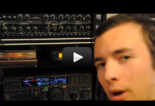
The videos on this page were created by Tyler, and his call sign is N7TFP. He’s extremely passionate about amateur radio, and he has created several videos on the hobby that I thought you might enjoy, including a peek at his radio shack. The “shack” refers to the place you do your “hamming”, usually in a shed or room where all your radio equipment is located. Some hams operate from their homes, others wire up their vehicles with portable radio stations, some hams set up a separate building in the yard, and a few had to be sneaky about hamming, especially if their housing development or family didn’t approve of their rooftop antennas. In fact, I know of one ham that was so desperate to continue his hobby, despite his wife’s objections that he stashed his radio equipment in a tiny closet and figured out a way to use the metal rain gutters as his antenna!


Let’s take a look at how a ham operator works:


If you’ve got your Amateur Radio License (we’ll talk more on how to do that later), you are ready to get on the air! First thing you should do is listen to how other hams do their communication so you can pick up on a few things. Different bands have different approaches to communication, so it really helps to hear a couple of exchanges before you make your first contact. Most people start with a Technician license with either a handi-talkie (hand-held transceiver) or a portable radio by going through something called a local “repeater”. Let me explain: The most popular way to communicate for a newly licensed ham to talk with other hams is through a local repeater. It’s a two-way radio system that receives communication on one frequency and then re-transmits what it hears on another frequency at exactly the same time. It’s simply a machine that relays your message since your transceiver has a limited range. It’s limited because of the size of the antenna and how the earth curves. A repeater can get your signal to reach a much further listener this way. There are repeaters all over the country. To make a contact on the 2 meter band through a repeater, I press the mike button and say:


    • “KJ6ZFH listening.” (Make sure you use your own call sign!). Now this may be all I need to do in order to get a response. But more often than not, there’s no response at all. So then I try again but add in a little more information like this:
  • “KJ6ZFH is monitoring and listening for a call.” Usually I don’t need to call CQ on a repeater, although there’s nothing in the rule books that say you can’t do that. I’ll tell you more about calling CQ in a moment.
  • When you get a response, it might sound something like this:
  • “KJ6ZFH this is W2AYL in St. George returning. My name is Pat. Back to you. W2AYL”. Then I’d wait for the repeater’s tone for the go-ahead to proceed with communication.
  • I’d press my mike button and respond, because now I’m in! Sometimes I give my name and location or any other info I want to talk to Pat about.
  • When I’m done talking, I say: “Over” or “Back to you.” I also make sure to give my call sign frequently (you’re required to do this every 10 minutes minimum). An easy way to do this is to tack it on at the end: “W2AYL this is KJ6ZFH. Over.”
  • When I’m done talking with Pat but still want to continue to monitor, I say goodbye by saying 73 (which means ‘best wishes’) and sign off like this: “W2AYL 73, this is KJ6ZFH clear and monitoring.”
  • If I’m done for the night, I would say: “W2AYL 73, this is KJ6ZFH clear and QRT” instead.

And that’s it! It’s really that simple. And it exciting and fun to keep track of all the different folks you get to talk with all over the country and world.


Make Contact by Calling CQ

“CQ” means “calling any station”. Some licenses permit you to operate on different bands, like SSB on 10 meters. Here’s what you’d do in this case: You always start by finding a clear frequency. Let’s say you’ve chosen to operate on 28.460. You want to speak clearly and ask “Is this frequency in use? This is KJ6ZFH.” If you don’t get a response, ask a second time just to be sure. If there’s still no response, you can continue. However, note that if the frequency is in use, just move to another frequency and try again.


Now you get to call: “CQ CQ CQ. This is Kilo Juliet Six Zulu Foxtrot Hotel calling CQ CQ CQ. This is Kilo Juliet Six Zulu Foxtrot Hotel, KJ6ZFH calling CQ and waiting for a call.” Wait and listen for a return call. If you’re on an HF (high frequency) band  like 10 meters, the signal you get back might be very strong to very weak or anything in between, so use your ears here.


You may hear “Kilo Juliet Six Zulu Foxtrot Hotel this is (their call sign) calling.” You respond by saying “(Their call sign, using phonetics) this is KJ6ZFH. Thanks for the call your signal is 59. My name is Aurora and my QTH is San Luis Obispo. So how do you copy? (Their call sign) this is KJ6ZFH over.”


You made HF (high frequency) contact! You can make the contact as you wish depending on the band conditions and what you find to discuss with your new friend in a new country!


Q Signals

Q signals are used primarily in CW. They provide an abbreviated way of asking a question or making a statement. A Q signal followed by a question mark (?) asks a question. A Q signal without the “?” answers the question or makes the statement.


The following are Q signals commonly used by CW operators world wide:


    • QSY – Shall I change to to transmission on another frequency? Change transmission to another frequency (or ___ kHz).
  • QTH – What is your location? My location is ___.
  • QRZ – Who is calling me? You are being called by ___ (on ___ kHz).
  • QSL – Can you acknowledge receipt? I am acknowledging receipt.
  • QSO – Can you communicate with ___ direct or by relay? I can communicate with ___ direct (or by relay through ___).
  • QRP – Shall I decrease power? Decrease power.
  • QRM – Is my transmission being interferred with? Your transmission is being interferred with ___. (1. Nil 2. Slightly 3. Moderately 4. Severely 5. Extremely)
  • QRN – Are you troubled by static? I am troubled by static —. (1-5 as under QRM)

You can find a complete list of Q signals here.


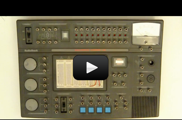
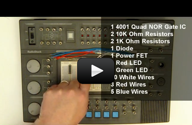
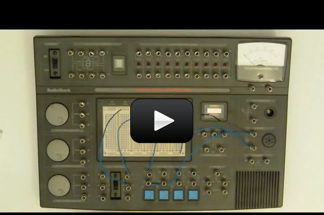
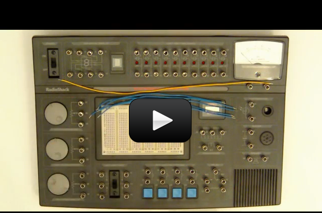
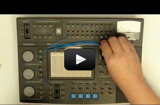
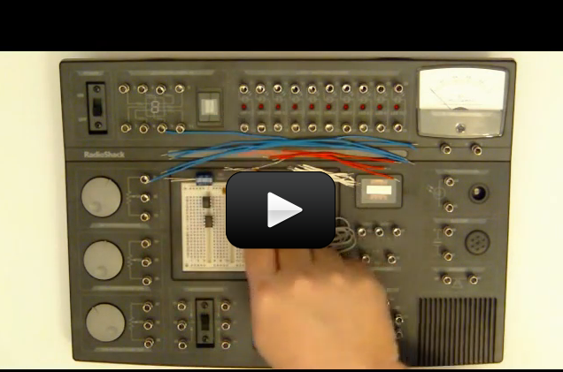
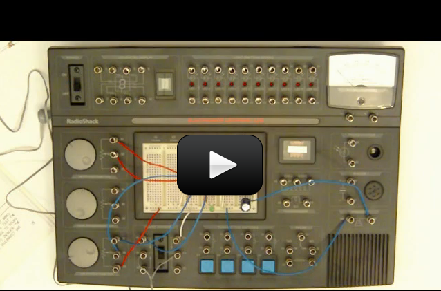
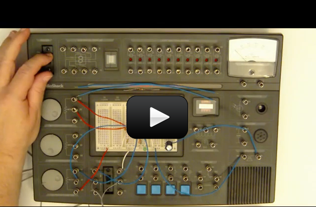
Building Your Amateur Radio Station

If you’re ready to build your own amateur radio station, here’s a video to get you started:


Your First Radio

This is a video on selecting your first radio. Some folks feel that a HT (handi-talkie, or hand-held transceivers) does not make good first radios, however for kids it’s a great first step into the hobby, and it’s not a huge investment… and it comes with the antenna and everything you need, all in one package. You can get a Baofang UV-5R if you’d like an inexpensive handi-talkie for about $60.


If you’d like a larger radio, get yourself a portable radio 30-60W in the 2 meter / 70cm bands – this will keep you busy for a long time. My first radio was the Yaseu 7900.


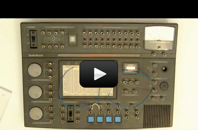
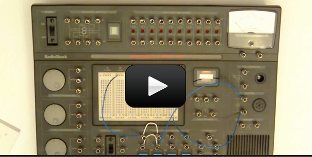
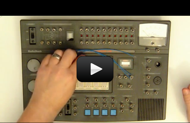
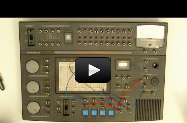
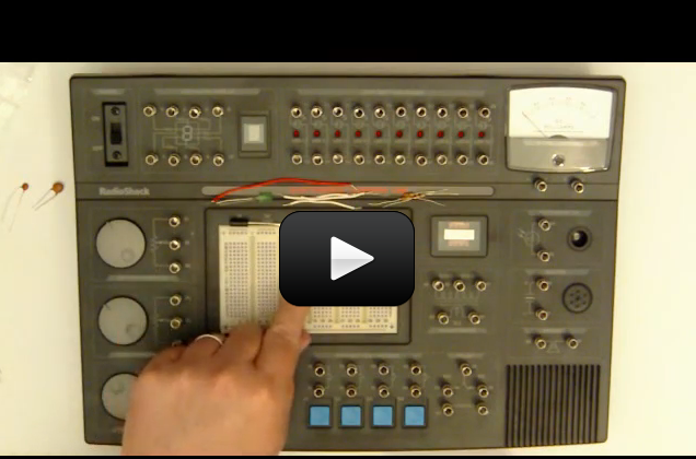
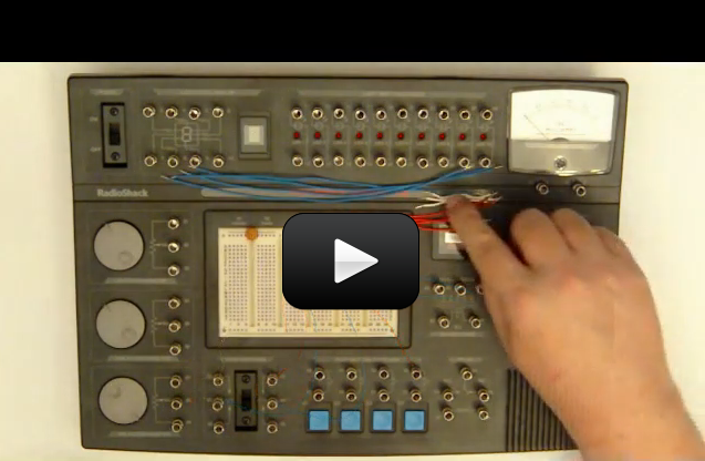
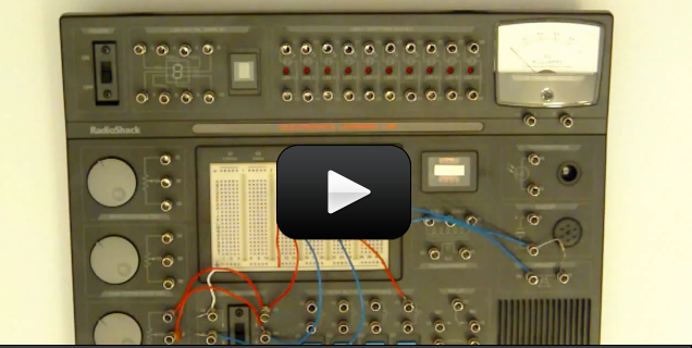
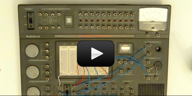
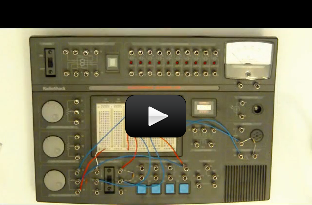
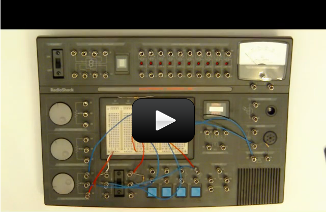
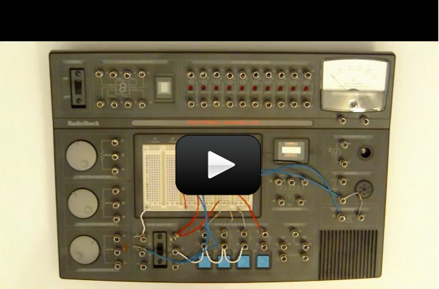
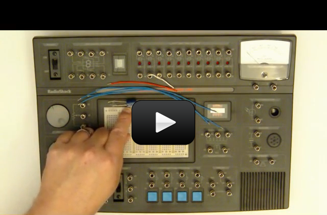
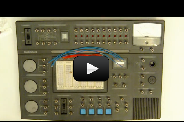
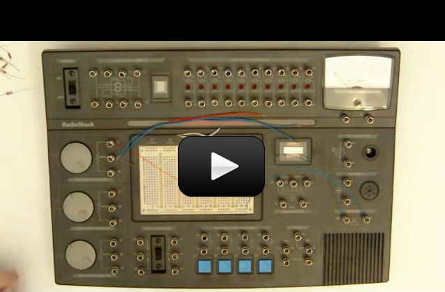
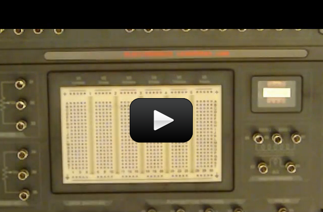
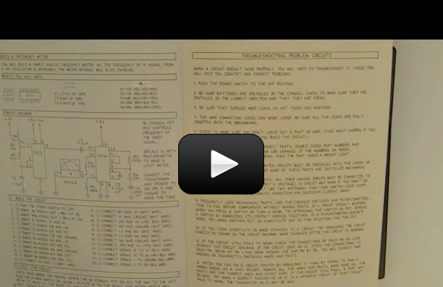
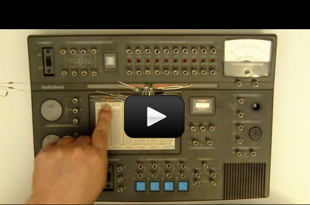
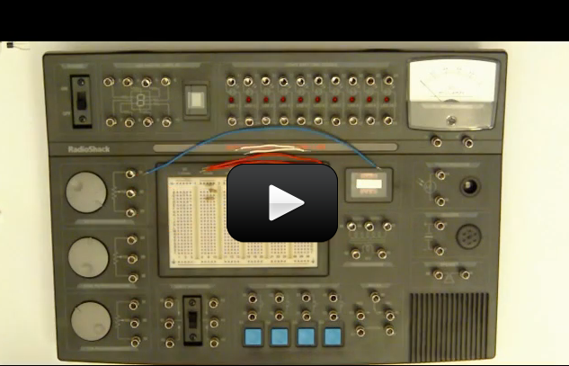
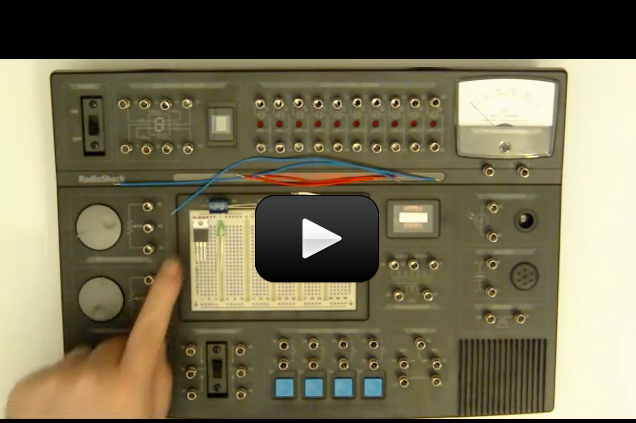
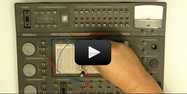
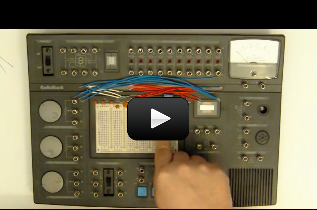
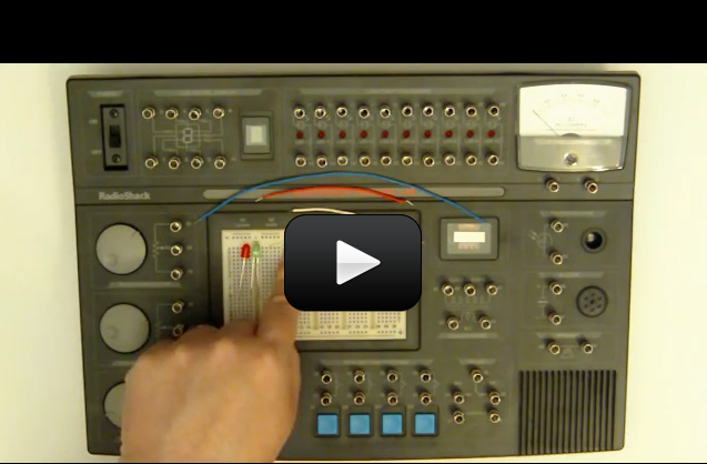
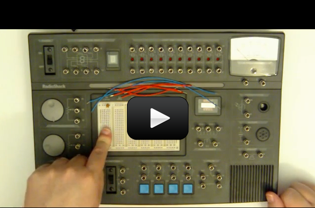
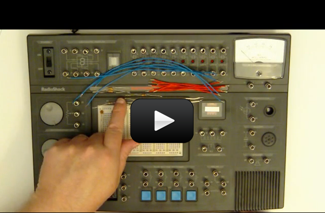
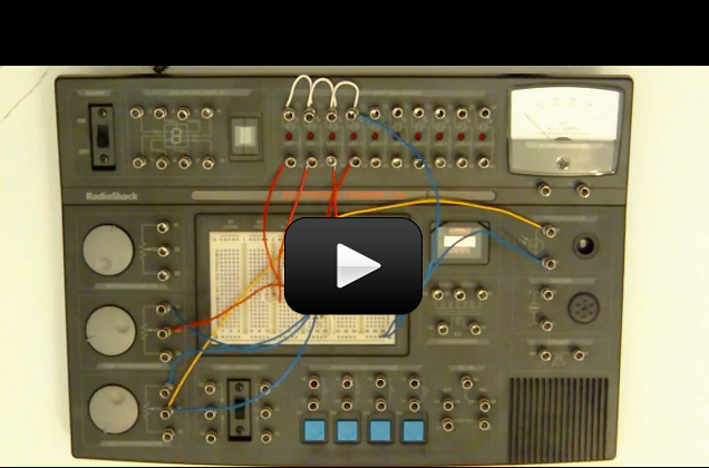
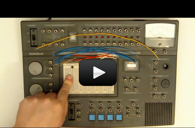
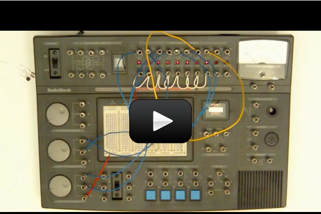
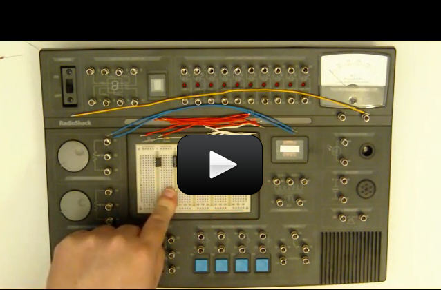
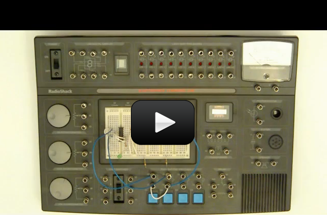
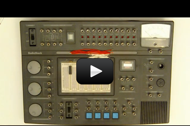
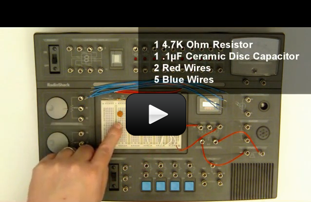
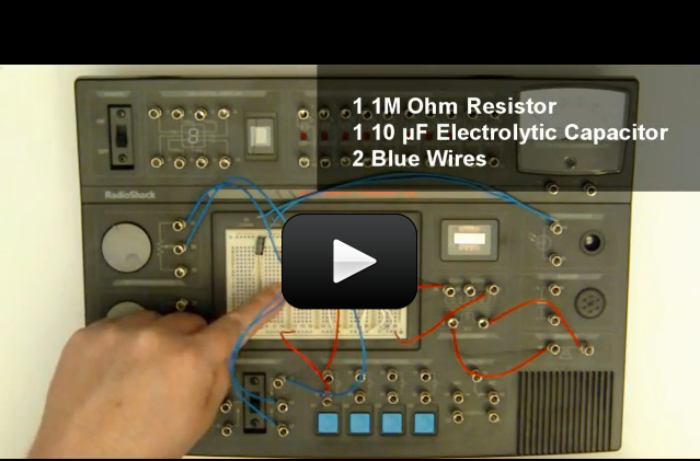
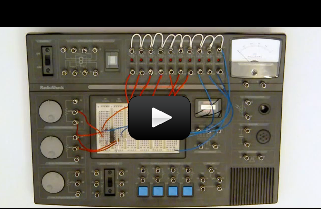
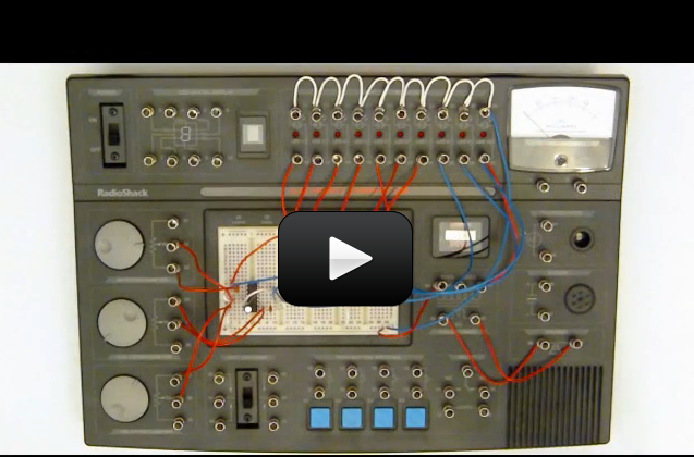
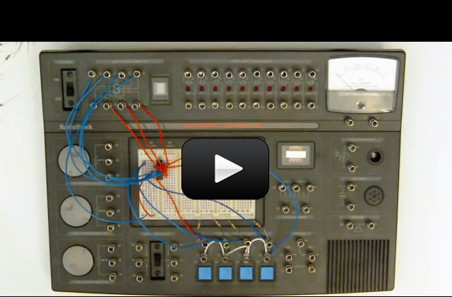
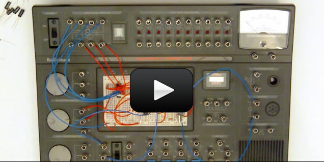
Sometimes, you’ll hear reference to the word “oscilloscope” or “o-scope”. If you’re wondering what it is, it an instrument used in the electronics/electrical fields (which includes radio) to help hams keep their equipment working properly. Most folks get their first exposure to one of these in a college level lab, but here’s sneak peek so you don’t have to wait. Here’s how it works:


The first thing you’ll want to do is set up your radio to the appropriate frequency, offset, CTCSS tone (if needed) so you’ll be ready to make your contact – all of this is covered in your instruction manual that comes with your radio.


Silly as this sounds, I spent to much time getting my equipment dialed in right that when it came time to speak, I clean forgot my call sign! I had to stick it (KJ6ZFH) on a post-it note right in front of me so I wouldn’t forget.


Getting Your Amateur Radio  License

After watching these videos and learning about radio communication, are you ready to get your license? If you’re excited about the idea, then NOW is a great time to jump on it. Would it surprise you to know that when I got my license, I woke up the morning of the test without even knowing that I was about to take the test? Not only that, I had not even cracked open an book on the subject? Sure, there are only 35 questions to answer, and they take them from a published pool of 350 questions, but honestly, it was a surprise date from my husband.


He drove me to a testing center where we studied for 5 hours, then took the test… all in a single day! No long weeks of studying theory, no late nights or giving up other activities… just a day of studying, take the test, and boom! I got my license. It cost me $20. So I totally encourage you to do it now while you’re excited and have momentum in this direction… that’s the moment you make the decision that takes you in a direction you really want to go. You can look up information on testing at the ARRL.


Enough said – here’s a quick video on getting your license you might find helpful:


Let’s see how much you’ve picked up with these experiments and the reading – answer as best as you can. (No peeking at the answers until you’re done!)  You can also print these out and jot down your answers in your science notebook.
Click here for a printer-friendly version of the exercises and answers for Unit 14.


Please login or register to read the rest of this content.

Let’s see how much you’ve picked up with these experiments and the reading – answer as best as you can. (No peeking at the answers until you’re done!) You can also print these out and jot down your answers in your science notebook.


Click here for a printer-friendly version of the exercises and answers for Unit 14.


Please login or register to read the rest of this content.

Let’s see how you did! If you didn’t get a few of these, don’t let it stress you out – it just means you need to play with more experiments in this area. We’re all works in progress, and we have our entire lifetime to puzzle together the mysteries of the universe!


Answers:
Please login or register to read the rest of this content.


Digital electronics can be a lot of fun and there are some really cool components in the market. So to get us going, in this video we’ll take a look at what digital is and start looking at how it works.


Please login or register to read the rest of this content.

Expanding on the first video for workbook 2, in this video we’ll take a look at logic gates, what they are, and how they work. This includes the AND gate, NAND gate, OR gate, and NOR gate.


Please login or register to read the rest of this content.

Time to start building some circuits, in this experiment we’ll use a 4049 hex inverter IC to build a simple logic probe. Logic probes are used to assist in debugging digital electronics.


Please login or register to read the rest of this content.

In this video we’ll take a look at truth tables, what they are, and why we need them. We’ll also build a simple circuit and construct a truth table from that circuit.


Please login or register to read the rest of this content.

Want to know how computers remember things? Well, in this experiment we will use two NOR gates to build a Set-Reset latch, which is a simple digital memory storage circuit.


Please login or register to read the rest of this content.

Okay, let’s get a little deeper into electronics and build a control gate. We’ll see how we can use a logic gate to control when a circuit is active and when it’s not.


Please login or register to read the rest of this content.

In this experiment we are going to combine a SR latch with an power FET and build a latched relay. And, we’ll see how we can use low power components to control high power circuits.


Please login or register to read the rest of this content.

In this experiment you’ll learn how to use the one of the Learning Lab’s push button swtiches to turn on the buzzer, then we’ll add in the DPDT (Double Throw Double Pole) switch to see how two switches can be used to control the buzzer.


Please login or register to read the rest of this content.

LEDs are a lot of fun, and in this experiment we’ll use the DPDT (Double Throw Double Pole) to turn on the buzzer and light up the LED while using a different voltage to control both of them.


Please login or register to read the rest of this content.

Did you know that the DPDT (Double Throw Double Pole) switch can control up to four different devices? In this experiment we’ll see how the DPDT switch can be used to control multiple devices at the same time!


Please login or register to read the rest of this content.

Switches are a lot of fun, they allow us to control when a circuit is on and when it’s off. In this experiment we’ll see how two switches can be connected in series to control when a single device is on or off.


Please login or register to read the rest of this content.


We’ve seen how switches can be used to turn stuff on and off, now let’s take a look at how a switch in different locations can turn the same thing on or off. A lot like a doorbell with a button at the front door and a button at the back door.


Please login or register to read the rest of this content.

Relays are really neat, they help us control high power circuits with low power circuits. In this experiment you’ll get to use the normally off contacts of the relay to control the buzzer using a switch.


Please login or register to read the rest of this content.

Did you know the relay also has normally closed contact as well? In this experiment we’ll see how these contacts differ from the normally open contact with the learning lab’s buzzer.


Please login or register to read the rest of this content.

We’ve seen how we can use the really to control the buzzer, now let’s use the relay as a buzzer! In this experiment we’ll see how to connect the relay to work as a buzzer. However, be careful the relay isn’t really designed to work like this for very long, but it’s okay for a short demonstration.


Please login or register to read the rest of this content.

Seeing electricity turn things on and off is a lot of fun, but we also need to have methods to see what’s going on in the circuit. What good is an alarm clock with numbers? Or a clock with no hands? In this experiment we’ll see how to use the learning lab’s meter to tell us what a circuit is doing.


Please login or register to read the rest of this content.

Now it’s time to learn about voltage dividers and in this experiment we’ll build one and use the meter to see what voltage the divider is supplying to the circuit.


Please login or register to read the rest of this content.

Yeah, it’s time to get back to some LED magic. In this experiment we’ll build an LED brightness control. We’ll be able to see the LED light up just a little or a whole lot.


Please login or register to read the rest of this content.

Photoresistors are a lot of fun, the can turn a circuit on or off based on how much light is getting to them. In this experiment we’ll see how a photoresistor can be used to turn an LED on or off.


Please login or register to read the rest of this content.

Wow, now it’s time to really get deeper into electronics and use our first IC in a circuit. IC stands for integrated circuit and the one we’ll be using is a legend in the electronics community. We are going to use a 555 timer to build an LED flasher!


Please login or register to read the rest of this content.

Ready to make some noise? We are going to build a “black box” test circuit using the 555 timer. A black box is a circuit that’s there when you need it, and in this one we will build it to produce a tone for us when we need it. Trust me, this one is a lot of fun.


Please login or register to read the rest of this content.

Our black box test circuit is capable of generating a lot of different sounds. In this experiment let’s take a look at how we can use resistors to generate different tones from our black box!


Please login or register to read the rest of this content.

Really ready to hear some weird sounds from the black box test circuit? Well, in this experiment we’ll modify the black box to use the photoresistor to generate sounds with our black box, and trust me, you won’t want to miss this one!


Please login or register to read the rest of this content.

In this black box experiment let’s use the photoresistor to reduce the tone frequency our black box generates. And, if you remember from a previous experiment the photoresistor can help us make some really wild sounds!


Please login or register to read the rest of this content.

Wow, we’ve had a lot of fun making strange sounds from the black box. Now, let’s try something a little different. In this experiment we’ll setup three push button switches to generate tones for us, with each switch giving us a different tone.


Please login or register to read the rest of this content.

Making weird sounds from the buzzer is a lot of fun, so let’s do some more! In this experiment we’ll use a capacitor to make the buzzer “chirp” for us! And then we’ll switch things up a bit and make the buzzer “warbler”.


Please login or register to read the rest of this content.

The black box test circuit has been a lot of fun, and this next experiment is going to be a noisy one, too! In this experiment we’ll setup our black box test circuit to generate either a rising tone or a falling tone using two capacitors and two push button swtiches.


Please login or register to read the rest of this content.

Time for some more keyboard action with the “black box”, in this experiment we’ll create a keyboard that will allow us to control the tone frequency of our black box. This experiment is neat since you can use the keyboard to generate up to nine different tones.


Please login or register to read the rest of this content.

We’ve had a ton of fun making a whole lot of different sounds with our black box test circuit. Now, let’s get more specific and make a space gun sound effect with the black box!


Please login or register to read the rest of this content.

We can do even more sound effects with the black box and we’ve had a lot of fun doing it. Now, it’s time to create another sound effect and this time we’ll make a siren using the black box test circuit and a few other components.


Please login or register to read the rest of this content.

I just love LEDs, they are fun to look at and provide useful purpose of communicating information from the circuit to us humans. Your learning lab also has a seven segment display built in, so let’s take a look at this and see how it works.


Please login or register to read the rest of this content.

Did you know that the seven segment display can create a whole lot of different symbols and characters? In this experiment we’ll make a small square on the seven segment display and get a better feel for what the display can do!


Please login or register to read the rest of this content.

Transistors are powerful electronic components that help us control a circuit. You can think of a transistor as an electronic switch. And, in this experiment we’ll see how a NPN (negative, positive, negative) transistor works and how to use them.


Please login or register to read the rest of this content.

Did you know a transistor can be only partially on? Well, in this experiment we take a look at turning a NPN transistor only partially on to light an LED. We’ll be using a potentiometer to control the transistor and be able to adjust when the transistor is off, to partially on, to full on.


Please login or register to read the rest of this content.

Electronic devices can either use a little bit of power or a whole lot of power. Think of your microwave, it uses a lot of power, but a lamp only uses a little bit of power. We use relays to allow low power circuits to control more powerful circuits. And, in this experiment we’ll use a NPN transistor to turn on the relay, which in turn will operate the buzzer.


Please login or register to read the rest of this content.

Time to make more noise! In this experiment we are going to use two transistors to make an oscillator. An oscillator is a circuit that generates a frequency, a pulse of signals, and we’ll use the oscillator to drive the speaker. You’ll be able to hear the pulse our oscillator generates as a tone from the speaker.


Please login or register to read the rest of this content.

Resistors are a very important part of electronics, in fact without them we wouldn’t even have electronics. Resistors help us control the flow of current through a circuit and protect components from being damaged. This video talks about what resistors are, how to read them, and how to use them.


Please login or register to read the rest of this content.

When you wire up a circuit, it may not work right away. But don’t worry, even experience engineers face this problem, sometimes we don’t get it right the first time either! This video covers some basic steps you can take to track down problems and fix them.


Please login or register to read the rest of this content.

Let’s have some more audio fun. In this experiment we are going to build a two transistor audio amplifier using two NPN transistors. We’ll be able to use the earphone as a microphone and listen in on just about anything.


Please login or register to read the rest of this content.

Let’s take a look at a new electronic component, the Power MOSFET. Now, we don’t have to call them “MOSFET” all the time, we can just call them “FET” and most people do. A FET is a lot like a transistor, but works a bit differently and in this experiment we’ll take a look at a FET and learn about them and how to use them.


Please login or register to read the rest of this content.

Now it’s time to have some fun with timers. And in this experiment we’ll be using a power MOSFET and a timer circuit to control how long an LED stays lit.


Please login or register to read the rest of this content.

Now that we’ve made a timer using an LED, let’s change the circuit up a bit and use the timer to control the buzzer. More noise, yeah!


Please login or register to read the rest of this content.

Let’s take a moment and get a better understanding of the analog ICs included with your project learning lab. In this video we’ll take a look at those different ICs and get a better understanding of what they are, what they do, and how to use them.


Please login or register to read the rest of this content.

Now it’s time to listen in on some ants! Yes, I said ants! In this experiment we’ll be using two Operational Amplifiers, Op Amp for short, to build a super sensitive audio amplifier. This amplifier is so sensitive it can pick up very low sounds and amplify them so we can hear what’s going on.


Please login or register to read the rest of this content.

But there’s no LED, and you know I love LEDs, so let’s add an LED to the super sensitive audio amplifier to include an LED. And, we’ll use the LED to indicate how strong the signal the microphone (earphone) is picking up.


Please login or register to read the rest of this content.

Well, maybe not. The LED is nice and all, but it doesn’t really give us a good feeling for the strength of the signal. So, let’s change the circuit to use the meter instead. This will give us a better visual indicator of the signal strength and also allow us to assign a value to a sound picked up by the amplifier.


Please login or register to read the rest of this content.

We’ve had a lot of fun making a lot of different circuits, now let’s step it up a notch and build a percussion instrument synthesizer. This circuit will build on what we’ve learned so far and use a lot of different parts to create a synthesizer that will generate a plucked string or drum sound. Are you ready to make some more noise? I am!


Please login or register to read the rest of this content.

A comparators is a form of an Op AMP that can either be on or off. This may not sound useful, but you can do things with comparators that are very useful. To demonstrate this, let’s take a look at comparators, what they are, and how to use them. In this experiment we’ll get use a comparator to control two different LEDs, and when the comparator is off, one LED will glow and when the comparator is on the other LED will glow.


Please login or register to read the rest of this content.

Now, let’s take a closer look at Op Amps and what they can do. In this experiment we’ll use an Op Amp to generate a frequency and then use that signal to produce a sound from the speaker.


Please login or register to read the rest of this content.

Making sounds has been a lot of fun, so lets do some more! In this experiment we’ll use two Op Amps to build a tone mixer and I think you’ll be surprised at the sounds you can get out of this project!


Please login or register to read the rest of this content.

Oh, this one is about LED bargraphs, and you know I love LEDs. In this experiment we are going to build an LED bargraph and then use that bargraph to measure how much light is hitting the photoresistor. In essence, we are going to build an LED bargraph light meter!


Please login or register to read the rest of this content.

Let’s have some more fun with the photoresistor and build a buzzer that has two modes. The first will be the buzzer triggering off of light and the second will be the buzzer triggering off of darkness. This circuit is exactly how a laser eye alarm works and we can try this by setting the circuit up to trigger when someone walks through a door! I’m not waiting, I’m doing this one now!


Please login or register to read the rest of this content.

Did you like the bargraph experiment? Well, in this one we are going to build a bigger and better bargraph. In this experiment we’ll build a 8 segment LED bargraph that has a sensitivity adjustment. You know me and LEDs, so let’s get wiring!


Please login or register to read the rest of this content.

Let’s have some more 555 timer fun and build a keyboard oscillator. In this experiment we’ll use a 555 timer and 4 switches, each with a different value capacitor, to create up to 16 different tones.


Please login or register to read the rest of this content.

Did you know that VCO stand for Voltage Controller Oscillator? Well, in this experiment we are going to build one using a 555 timer, a few capacitors, and a potentiometer. We’ll then send the signal from the VCO to the speaker and make some neat tones!


Please login or register to read the rest of this content.

Timers are really neat, and we’ve already seen a few in action. Now, let’s build one that operate the buzzer and an LED and can run both for up to 100 seconds. We’ll be using a 555 timer, several capacitors, a potentiometer, and a few switches as well. Sound like fun to me!


Please login or register to read the rest of this content.

We’ve created a lot of circuits together and now it’s time to start looking at a new part, the 4046 is a Phased-Locked Loop IC that contains both analog and digital circuitry inside. Well be using the 4046 to help generate the siren sound for this circuit. We’ll also be using the 555 timer and all the potentiometers in the kit. So let’s get started and build us a siren!


Please login or register to read the rest of this content.

Now, let’s have some more LED fun. In this experiment we’ll see how to use three inverters to build a dual LED flasher.


Please login or register to read the rest of this content.

Want to see how computers add? Well, in this experiment we are going to use a exclusive OR gate to build a binary half adder to get an idea of how computers add numbers. This is a critical lesson in understanding binary and how binary numbers are added together, we’ll also expand on this experiment in the next video.


Please login or register to read the rest of this content.

Let’s take a closer look at the NAND gate and how it works, so in this experiment we’ll build a circuit to test the NAND gate and also create a truth table to prove the NAND gate is working correctly.


Please login or register to read the rest of this content.

If you enjoyed these experiments, then you’re in for a real treat, because there’s a lot MORE experiments in Lesson 4: Digital Logic!


Since the mid 1980’s, digital electronics have slowly become an ever increasing part of our lives. And now, you’d be hard pressed to find any device that doesn’t use digital electronics. Digital electronics are in the TV you watch, your computer, your phone, your car, the appliances in your kitchen, and so much more. So, to help understand how digital works, we’ll be exploring digital electronics in this series of videos.
We are going to cover a lot of ground in workbook 2 beginning with learning about the basics of digital electronics. This will include learning what a bit is, what a high and a low are, basic digital gates, among other topics.


Click here to view the next set of experiments in Electronics.


More LED fun! In this experiment we’ll see who we can combine a 555 timer, a single NAND gate, and make an alternating LED flasher. This circuit will alternate (turn on and off) a green LED and a red LED.


Please login or register to read the rest of this content.

There are a lot of different types of logic gates and in this experiment we’ll see how we can use three NAND gates to make an OR gate. And then we’ll test the gate and create a truth table to prove that the OR gate is working correctly.


Please login or register to read the rest of this content.

Let’s make some noise! In this experiment we’ll use two NAND gates to create a simple oscillator and tie that into the speaker and we’ll see how easy it is to make a tone generator using just a few parts.


Please login or register to read the rest of this content.

The tone generator is nice, but we can make it better. So, in this experiment we’ll modify the tone generator from page 46 of workbook 2 to have an adjustable frequency and volume.


Please login or register to read the rest of this content.

Let’s take the tone generator a step further and add in a second frequency generator and pulse the tone out to the speaker. In this experiment we’ll see how to do just that.


Please login or register to read the rest of this content.

A half-adder is nice, but it’s not providing all the information we need to fully see what’s going on. So, in this experiment we’ll build upon the half-adder from experiment 53 in workbook 2, and turn the half-adder into a full-adder.


Please login or register to read the rest of this content.

Digital locks are pretty neat and in this experiment we are going to build one. We’ll use a lot of different logic ICs to build a digital comparator, which can be used as a combination lock to protect valuables.


Please login or register to read the rest of this content.

Your Electronics Learning Lab includes a 4066 switch IC and in this video we’ll take a look at how this IC works by building a simple LED indicator circuit.


Please login or register to read the rest of this content.

Okay, let’s dive a little deeper into digital memory by taking a look at a data type flip-flop. We’ll see how this logic IC works by building a simple LED display interface and control the flip-flop using switches.


Please login or register to read the rest of this content.

Would you like to see a digital circuit do a little division? Well, in this experiment we’ll build on our knowledge and build a divide-by-two circuit using an inverter IC the 4013 D-type flip-flop. This circuit is also the basis for the LED chaser circuit we’ll build later in the series.


Please login or register to read the rest of this content.

Let’s take a look at binary addition and build a 2-bit counter. In this experiment we’ll modify the divide-by-two circuit we built in the last video to a 2-bit binary counter.


Please login or register to read the rest of this content.

Time for some light chasing fun. In this experiment we’ll modify the divide-by-two circuit form the last video to an LED chaser circuit. This one is really neat and I’m personally excited to see this one in action!


Please login or register to read the rest of this content.

Did you know switches are noise? And no, I don’t mean the noise they make when you turn one on or off, I mean they are electrically noisy. What this means is that when a switch changes state is creates a little wave of electrical spike that can cause digital electronics to misread the signal. In this experiment we are going to build a switch bounce analyzer to help see the noise.


Please login or register to read the rest of this content.

Now that you’ve seen switch noise, it’s time to look at a method to correct the problem. So in this experiment we are going to build a totalizer and add a capacitor to the switch to remove switch noise.


Please login or register to read the rest of this content.

In this experiment we’ll modify the totalizer we built in the last experiment to a count-to-n and halt circuit. This is a great demonstration of using electronics to operate a circuit until a specific number of events has occurred.


Please login or register to read the rest of this content.

The bargraph readout from the previous experiment is nice, but let’s make it better. In this experiment we’ll use three oscillator circuits to control the bargraph’s settings and also add in a tone generator.


Please login or register to read the rest of this content.


It’s been sitting there, and we’ve hardly touched the seven segment display. Well, in this video we are going to use the 4511 seven segment decoder to drive the seven segment display and a keypad to display different numbers. This one is going to be a lot of fun!


Please login or register to read the rest of this content.

Let’s build a digital alarm! In this experiment we’ll modify the circuit from experiment 90, workbook 2, to be a digital alarm. The circuit will countdown and when it reaches zero, the alarm will sound. We’ll also add in a switch so that the alarm part of the circuit can be disabled.


Please login or register to read the rest of this content.

This Lesson is for advanced students. Most people who learn about electronics start by studying the theory of how electric current flows through wires and other stuff that conducts electricity, called conductors. Unfortunately this stuff is BORING! I mean, I can’t stand it myself sometimes. So, we’re going to start with what I call “Lego brick” electronics.


You’re going to start by building cool things, then learn what each part of the circuit does, but not go into the minute details. You’ll learn how to build circuits out of electronic “bricks” like you can build something out of Lego bricks. You don’t need to design your own Lego bricks, but just focus on using them. Same thing here – you’ll learn how to put pieces together to build circuits. Our pieces are electronic components. Things like transistors, resistors, integrated circuits (chips), capacitors and lots more.


Although you can’t see electricity, you can certainly detect its effects – a buzzer sounding, a light flashing, a motor turning… all of these happen because of electricity. Which is why electricity experiments are among the most frustrating. You can’t always tell where the problem is in a circuit that refuses to work right.
We’re going to outline the different electronic components (resistors, capacitors, diodes, transistors, etc) so you get a better feel for how to use them in a circuit. While we’re not going to spend time on why each of these parts work (which is a topic best reserved for college courses), we are going to tackle how to use them to get your circuit to do what you want. The steps to building several different electronics projects are outlined very carefully so you can really understand this incredible micro-world.


Please login or register to read the rest of this content.

Electronics are used everywhere these days. Of course, we see them in TV’s and stereos, computers, cell phones and iPods. But they’re also a part of car keys and even mailing labels on boxes.


They’re used to explore the surface of mars in space probes and give sight to blind people. All these things use transistors, resistors, chips and more – just what we’ll be talking about in this unit. So, let’s get started.


Please login or register to read the rest of this content.