Ever play with a prism? When sunlight strikes the prism, it gets split into a rainbow of colors. Prisms un-mix the light into its different wavelengths (which you see as different colors). Diffraction gratings are tiny prisms stacked together.
When light passes through a diffraction grating, it splits (diffracts) the light into several beams traveling at different directions. If you’ve ever seen the ‘iridescence’ of a soap bubble, an insect shell, or on a pearl, you’ve seen nature’s diffraction gratings.
Scientist use these things to split incoming light so they can figure out what fuels a distant star is burning. When hydrogen burns, it gives off light, but not in all the colors of the rainbow, only very specific colors in red and blue. It’s like hydrogen’s own personal fingerprint, or light signature.
While this spectrometer isn't powerful enough to split starlight, it's perfect for using with the lights in your house, and even with an outdoor campfire. Next time you're out on the town after dark, bring this with you to peek different types of lights - you'll be amazed how different they really are. You can use this spectrometer with your Colored Campfire Experiment also.
SPECIAL NOTE: This instrument is NOT for looking at the sun. Do NOT look directly at the sun. But you can point the tube at a sheet of paper that has the the sun’s reflected light on it.
Here's what you do:
[am4show have='p8;p9;p25;p52;p105;p91;p101;' guest_error='Guest error message' user_error='User error message' ]
Download Student Worksheet & Exercises
You will need:
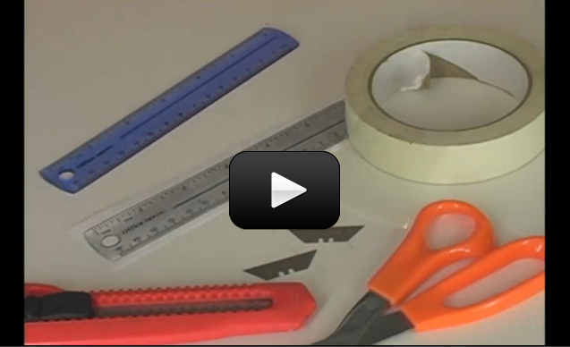
- cardboard box (ours is 10" x 5" x 5", but anything close to this will work fine)
- linear diffraction grating (you can order one here)
- 2 razor blades (with adult help)
- masking tape
- ruler
- photocopy of a ruler (or sketch a line with 1 through 10 cm markings on it, about 4cm wide)
1. Using a small box, measure 4.5 cm from the edge of the box. Starting here, cut a hole for the double-razor slit that is 1.5 cm wide 3 cm long.
2. From the other edge (on the same side), cut a hole to hold your scale that is 11 cm wide and 4 cm tall.
3. Print out the scale and attach it to the edge of the box.
4. Very carefully line up the two razors, edge-to-edge to make a slit and secure into place with tape.
5. On the opposite side of the box, measure over 3 cm and cut a hole for the diffraction grating that is 4 cm wide and 3 cm tall.
5. Tape your diffraction grating over the hole.
Aim the razor slit at a light source such as a fluorescent light, neon sign, sunset, light bulb, computer screen, television, night light, candle, fireplace… any light source you can find. Put the diffraction grating up to your eye and look at the inner scale. Move the spectrometer around until you can get the rainbow to be on the scale inside the box.
How to Calibrate the Spectrometer with the Scale Inside your box is a scale in centimeters. Point your slit to a fluorescent bulb, and you'll see three lines appear (a blue, a green, and a yellow-orange line). The lines you see in the fluorescent bulb are due to mercury superimposed on a rainbow continuous spectrum due to the coating. Each of the lines you see is due to a particular electron transition in the visible region of Hg (mercury). The blue line (435 nm), the green line (546 nm), and the yellow orange line (579 nm). (If you look at a sodium vapor street light you'll see a yellow line (actually 2 closely spaced) at 589 nm.)
Step 1. Line the razor slits along the length of the fluorescent tube to get the most intense lines. Move the box laterally (the lines will move due to parallax shift).
Step 2. Take scale readings at the extreme of the these movements and take the average for the scale reading. For instance, if the blue line averages to the 8.8 cm value, this corresponds to the 435 nm wavelength. Do this for the other 2 lines.
Step 3. On graph paper, plot the cm ( the ruler scale values) on the vertical axis and the wavelength (run this from 400-700 nm) on the horizontal axis. Draw the best straight lines thru the 3 points (4 lines if you use the Na (sodium) street lamp). You've just calibrated the spectrometer.
Step 4. Line the razor slits up with another light source. Notice which lines appear and where they are on your scale. Find the value on your graph paper. For example, if you see a line appear at 5.5 cm, use your finger to follow along to the 5.5 cm until you hit the best-fit line, and then read the corresponding value on the wavelength axis. You now have the wavelength for the line you've just seen!
Notes on Calibration and Construction: If you swap out different diffraction gratings, you will have to re-calibrate. If you make a new spectrometer, you will have to re-calibrate to the Hg (mercury) lines for each new spectrometer. If you do remake the box, use a scale that is translucent so you can see the numbers. If you use a clear plastic ruler, it may let in too much light from the outside making it difficult to read the emission line.
What other light sources work? Use your spectrometer to look at computer screens, laptops, night lights, neon lights, candles, campfires, fluorescent lights, incandescent lights, LEDs, stoplights, street lights, and any other light sources you can find. When you walk down town at night and look at various "neon" signs. Ne (neon) is a real burner! Do this with a friend who is willing to vouch for your sanity.
Question: What happens when you aim a laser through a diffraction grating? (See picture above - can you find the two dots on either side of the main later dot?)
[/am4show]
Sorry about that – I’ve updated the link!
The link for the diffraction grating is no longer correct. Is there another place we can purchase this?
Yes, but not for this particular experiment. You’ll want to make the other spectrometer in this section – it specifically calls for a CD to be used in the diffraction grating’s place. 🙂
Is it possible to substitute a cd for a diffraction grating?
Aurora: Great video on the spectrometer! Well documented and step by stepped. I did have a few recommendations.
When you cut the hole for the Xeroxed scale be sure that it is aligned with and perpendicular to the center of the slit to get the image centered on the scale. This will ensure the emission line will cover the scale.
Also, when you attach the grating, one of the most common mistakes is to rotate the grating 90 degrees and the emission lines will not be vertical on the scale. The lines on the grating must be parallel to the slit. It’s kind of hard to see this before you attach it so I’d only used 2 small pieces of tape initially to attach the grating, look inside to be sure you have lines on the scale, and then firmly attach the grating. Or you could mention that if you don’t see lines, rotate the grating by 90 degrees.
I’d also change the vertical scale on the calibration chart from 0-10 cm down to 5-10 cm so you get a greater negative slope and better resolution on the calibration curve.